C.D.S. Newsletter July 2010
In this issue...
- Modeling Ventilation Rates for LEED
- Building Information Modeling (BIM), TOPSS, and TRACE
- Trane Offers LEED Credential Maintenance Courses Online
- Did You Know...?
- Frequently Asked Support Questions
- Meet the C.D.S. Support Staff...Shawn O'Brien
Modeling ventilation to meet LEED v3 requirements
USGBC’s Leadership in Energy and Environmental Design (LEED) program updates its products to closely align with the latest industry standards. LEED version 3, the most recent version of LEED (also known as LEED 2009) incorporates the latest standards such as ASHRAE 90.1-2007 and ASHRAE 62.1-2007.
Members of the C.D.S. support group are involved with and often contribute to ASHRAE and diligently work to update TRACE 700 software to reflect the latest changes in ASHRAE standards and LEED. TRACE 700 can model the ventilation in the proposed and baseline buildings to meet the requirements of LEED version 3. Specifically, TRACE 700 can be used to meet the following requirements:
- IEQ Prerequisite 1
Requires ventilation to meet the requirements of ASHRAE Standard 62.1-2007*.
- EA Credit 1 – Option 1: Whole Building Energy Simulation
Requires the baseline building’s performance to be calculated according to Appendix G.3.1.2.5 of ASHRAE Standard 90.1-2007, which reads: "Ventilation. Minimum outdoor air ventilation rates shall be the same for the proposed and baseline building designs."
To meet both of these requirements in TRACE 700, follow the steps below.
1. Model the ventilation in the proposed alternative following the steps shown in the “ASHRAE Standard 62.1” section of the TRACE 700 User’s Manual (beginning on page 4-91).
2. Next, run the design calculations of the proposed alternative to obtain the total building outdoor airflow (the airflow for each system can be found in the System Checksums report).
3. Divide that number by the square footage of the building. This will provide a cfm/sq ft value to be applied as the cooling and heating ventilation rate for all rooms in the Baseline alternative, preferably using templates.
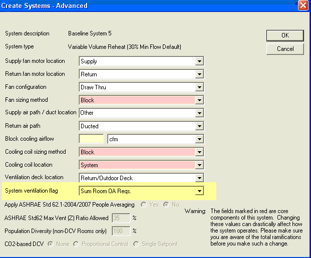
4. Finally, for the Baseline alternative, set the Standard 62.1-2004/2007 inputs in Create Templates and Create Rooms to “No,” to prevent the program from running the Standard 62.1-2007 zone calculations again. Set the cooling and heating ventilation inputs to the cfm/sq ft rate from Step 3. In addition, go to Create Systems, click Advanced, and set the system ventilation flag to "Sum Room OA Reqs" in the Baseline alternative to prevent the program from running multi-zone calculations of Standard 62.1-2007 (see screen shots below).

*The above procedure applies to projects that are following ASHRAE Standard 90.1-2007 (without addenda) and have defined the ventilation in the Proposed alternative based on Standard 62.1-2007. Addendum DA to Standard 90.1-2007 had its first public review in February 2010 and has an exception that states that if the Proposed alternative is designed based on the Ventilation Rate Procedure in Standard 62.1, then the Baseline alternative shall also be calculated using the Ventilation Rate Procedure with the following change: “Baseline zone air distribution effectiveness shall be changed to (Ez)=1.0 per each Proposed zone having a zone air distribution effectiveness (Ez)>1.0." Addendum DA will be voted on in an upcoming ASHRAE meeting and might be included in 90.1-2010. If this happens, then the above procedure will not apply to any project that will follow ASHRAE Standard 90.1-2010.
For more information about ventilation standards, view our Engineers Newsletter Live webcast, ASHRAE Standards 62.1 and 90.1, and VAV Systems.
Building Information Modeling (BIM), TOPSS, and TRACE 700
BIM means different things to different people. For some, BIM simply describes objects imported into a CAD file. To others, the concept encompasses managing information from the earliest part of the design phase to the completed life cycle of the building. This article highlights two features offered by TRACE 700 to help manage data effectively, no matter your definition.
Import equipment selections made in Trane’s selection program, TOPSS, into TRACE or your CAD program. Importing TOPSS selections into TRACE ensures a more accurate energy model because it uses actual equipment parameters. This streamlines the equipment creation process in TRACE eliminating the need to manually build power consumed and ambient relief curves. TOPSS users have access to export any of the rotary chiller equipment selections. CenTraVac equipment selections can be accessed through your Trane Sales Engineer.
Additionally, TOPSS has a BIM feature that allows you to export the equipment selection to a compatible CAD program (e.g. Revit, Bentley).
In order to use the TOPSS export feature, you must have a full version of TOPSS. Contact your Trane Sales Engineer for a free copy of the software.
Import a compatible CAD file into TRACE. TRACE can import CAD files formatted as gbXML (Green Building XML). This functionality offers several modeling advantages:
- Importing a CAD file into TRACE is a quick and easy way to define a building and its zoning, and it ensures you are using the same parameters throughout the design process.
- TRACE offers advanced airside systems (e.g. underfloor air distribution, variable refrigerant volume, chilled beams) and centralized geothermal systems that allow you to explore various options to optimize the building’s performance.
- Although CAD programs have begun to add some energy modeling capabilities, they do not offer the extensive load and energy calculations found in TRACE. Leveraging TRACE’s calculations results in a highly accurate analysis.
- Just like TOPSS selections, results from the TRACE calculations can be exported back to the CAD file. This allows you to bring calculated results back into your CAD program.
To import CAD files into TRACE, open TRACE and select “Import gbXML” from the File menu. Refer to the TRACE 700 User’s Manual for details regarding the information imported into TRACE and for detailed instructions. Additional questions may then be addressed via email or over the phone with the C.D.S. support center.
More articles on TOPSS:
Trane now offering LEED credential maintenance courses online
Continuing education courses are now available online at www.trane.com/continuingeducation. Since becoming a U.S. Green Building Council (USGBC) Education Provider in February 2010, Trane has been adding LEED credential maintenance courses on a monthly basis to equip LEED professionals with the continuing education needed to stay competitive in the sustainable building industry.
These courses are offered at no charge and range from fan basics to ASHRAE Standards 62.1 and 90.1. The following courses include specific TRACE 700 analyses:
- Central Geothermal System Design and Control
- Energy-Saving Opportunities for LEED® and the Energy Policy Act
- Air-Handling Systems, Energy and IAQ
The automated online process allows you to view the course webcast, take an assessment quiz and download a certificate of completion. Each course includes course material, presenter biographies and bibliographies for further research.
All courses are approved by USGBC/GBCI and AIA and provide up to 1.5 CEUs.
Did you know that the TRACE 700 User's Manual is updated with each release of TRACE? You can access the latest version from TRACE by selecting the Help menu, clicking Documentation, and then clicking User's Manual.
The TRACE 700 User’s Manual provides more than 400 pages of information on how to model specific scenarios. The first two sections include basic information and an overview of the program phases. The remaining sections delve into detailed aspects of how to model different applications. A modeling guide for LEED® is also included. This is an invaluable resource in which you can find answers to many of your questions.
Frequently Asked Questions
How do I model a system with 100% outdoor air in TRACE?
Systems that require 100% outdoor air are common in hospitals and laboratories. This system is the only equipment serving the assigned zones.
Modeling a system with 100% outdoor air can be done on a room-by-room basis on the Create Rooms-Airflows tab, or it can be done for all the rooms at once on the Create Templates-Airflow tab. Note: For a system to be 100% outdoor air, all rooms assigned to the system must be specified as 100% outdoor air.
To model a 100% outdoor-air system, complete the following steps:
Step 1: Access the Airflow tab of Create Rooms or Create Templates.
Step 2: In the Ventilation section, select 100 Percent Outdoor Air from the drop-down list in the Type field. The Cooling and Heating fields default to 100% Clg Airflow and 100% Htg Airflow, respectively.
Step 3: If a minimum airflow must be supplied to the space, input the minimum airflow rate under the Main Supply section, using the units of air changes/hour, cfm/sq ft, L/s/sq m, cfm/person, or L/s/person. By default, TRACE will calculate the supply airflow based on the loads for the space.
Step 4: If a VAV system is being modeled, input the heating minimum airflow rate in the Rate field in the VAV Minimum section.
Step 5: If 0% return air is being modeled, enter 100% Clg and 100% Htg Airflow in the Rate field in the Room Exhaust section to exhaust the air at room level.
Step 6: In Create Systems, select the appropriate airside system, associated fans, static pressures, and supply-air temperature ranges for the system.
Step 7: Assign the rooms to the airside system and calculate the design results for the air handler.
How do I model a water-source heat pump in TRACE?
Water-source heat pumps (WSHPs) transfer heat from air to water and vice versa. Piping the heat pumps together in a common water loop creates a heat-recovery system that can redistribute heat where it is needed—for example, from interior zones to perimeter spaces.
Within TRACE, there is a specific water-source heat pump airside system to use, as well as standard pre-built cooling equipment. Although water-source heat pumps provide both cooling and heating, in TRACE they are considered a cooling piece of equipment with a reversing valve. This means that the Create Plants section of the program has some modeling nuances that require special attention. Also note that dedicated outdoor air systems are commonly used in conjunction with water-source heat pumps to provide ventilation air to the space or heat pumps.
To model a WSHP, follow these steps:
Step 1: On the Create Systems - Selection screen, select Water Source Heat Pump as the system type and click Apply.
Step 2: On the Fans tab, select Hydronic in Heat Pump Fan as the fan type in the Primary field, and enter the static pressure.
Step 3: On the Create Plants screen, select the WSHP equipment and drag it to the appropriate cooling plant. Note that TRACE will not allow you to assign a WSHP piece of equipment to a heating plant because in TRACE it is considered a cooling piece of equipment by definition. Rename the cooling plant as WSHP.
Also note that all heat pump or heat recovery systems in TRACE require a backup heat source. TRACE will therefore require that a backup heating piece of equipment be assigned to the heating plant.
Step 4: Select the cooling plant and click the Cooling Equipment tab.
Step 5: Choose the specific water-source heat pump equipment that best matches the target performance.
Step 6: Enter the Full-Load Consumption of the pump that serves the common water loop—the primary chilled-water pump, in this case. Keep in mind that the pump works as both a condenser and primary chilled water pump due to its reversible nature, but TRACE simply categorizes this pump as chilled-water.
Step 7: Click Controls to assign the excess heat from the common water loop to loads served by the heating plant identified as the Energy Source. Note: Do not remove thermal storage as this will eliminate the water loop from the simulation.
In the case of heating, TRACE will first use whatever heat it can recover from the water loop before activating the backup heat source.
Step 8: Be sure to apply your changes. On the Heating Equipment tab, pick the boiler equipment that most closely matches the anticipated performance.
Step 9: Enter the Full-Load Consumption of the pump that circulates hot water from the boiler.
Step 10: Assign each coil load to the appropriate plant.
Note: When viewing the equipment energy consumption report for heat pump systems, keep in mind that all compressor energy reflected for both heating and cooling will be displayed in the cooling equipment section of the report only. Only backup heating energy (if necessary) will be reflected for the heating plant.
For more information, the attached excerpt from the TRACE User's Manual discusses how to model a water-source heat pump system in TRACE 700.
Meet the C.D.S. Support Staff... Shawn O'Brien
Shawn is a new marketing engineer in the C.D.S. department. He graduated from the University of Wisconsin-La Crosse in 2005 with a B.S. in Physics. Since then, he has worked as a design engineer for two companies and helped out in one of his family’s businesses. Shawn is a Wisconsin Army National Guard member and was deployed to Iraq from 2009-2010.
Q. What three items would you want if stranded on a desert island?
A fishing pole, sunscreen, and a flag to stake on it proclaiming it as “My Island."
Q. What is the most enlightening book you've read in the past year?
The Story of the Irish Race: A Popular History of Ireland by Seumus MacManus. Thumper thick book, but now I know more about myself and history.
C.D.S. Newsletter October 2010

