C.D.S. Newsletter April 2012
TRACE 700 Version 6.2.8 Available
Download update
TRACE 700, Load Design, Load Express, and Chiller Plant Analyzer updates are now available. The articles below detail the newest features in version 6.2.8. View the complete list of changes.
- Single Zone VAV System
- Dual VAV Control Strategy Added
- Two Ice Storage Templates Added to Chiller Plant Analyzer, TRACE Plant Wizard
- New COMNET XML File Export Functionality
- Equipment Added to Libraries
The single zone variable-air-volume (SZVAV) system type has been added to TRACE to provide our customers with the latest HVAC design functionality. Single zone VAV is a prescriptive requirement of ASHRAE Standard 90.1-2010, Section 6.4.3.10. ASHRAE Standard 90.1-2010 will be a prerequisite to achieve LEED 2012 certification. Effective January 1, 2012, both ASHRAE Standard 90.1 and California Code Title 24-2008 extend the requirement for the inclusion of VAV to single zone direct-expansion units greater than or equal to 110,000 Btu/h.
For more information about the requirements, refer to the following:
- ASHRAE 90.1 Addenda [PDF] (refer to Addendum N on p. 50)
- California Code Title 24 [PDF] (refer to Section 144-L on p. 108)
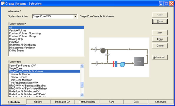
System Description
A single zone VAV system consists of a variable-volume fan, a direct-expansion or chilled-water cooling coil, and a heating coil. A temperature sensor in the zone is used to directly vary the volume of supply air delivered by the fan. Just like in a conventional VAV system, cooling capacity is modulated to maintain the discharge-air temperature at a setpoint. This system is mainly applied in zones where occupancy varies throughout the day, such as gymnasiums and auditoriums. Compared to a constant-volume system that is often used for large zones such as these, a single zone VAV system results in fan energy savings at part-load conditions.
Selecting it in TRACE 700
The single zone VAV system is available on the Create Systems-Selection screen. Click Variable Volume in the System Category box and Single Zone Variable Air Volume in the System Type box. On the Fans tab, select a variable-volume primary fan.
The coils and fan are located at the zone level. If the rooms are assigned directly to the single zone VAV system, then an air-handling unit is assigned to each room. If you have more than one room served by the equipment, create a zone for the system and assign the rooms to that zone.
Dual VAV Control Strategy Added
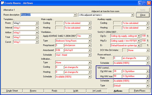
The new dual VAV control strategy is a method to control VAV terminal-reheat units in TRACE 700. Previously in TRACE, you could only specify the minimum amount of main supply airflow for a variable-volume terminal box, which applied to both the cooling and heating modes. With this update, we have added new fields for the cooling VAV minimum and heating VAV maximum setpoints. TRACE can then determine the airflow damper modulation for each mode of operation.
The new fields, Clg VAV min and Htg VAV max, are located on the Airflows tab of Create Rooms and Create Templates. (They replace the VAV Minimum Rate field.) Select the values and units for each field, as well as the schedule and type.
How does it work?
When the zone requires cooling, the primary airflow is varied between maximum and minimum cooling airflow, as required to maintain the desired temperature in the zone.
When primary airflow reaches the minimum cooling airflow setting, and the cooling load continues to decrease, the heating coil is activated to warm the air to avoid overcooling the zone. As more heat is needed, the controller resets the discharge-air temperature setpoint upward to maintain zone temperature at setpoint (dark, dashed line in Figure 1), until it reaches a defined maximum limit. The discharge temperature is limited to minimize temperature stratification when delivering warm air through overhead diffusers.
When the discharge-air temperature reaches the maximum limit and the zone requires more heating, primary airflow is increased until it reaches a maximum heating airflow setting, while the discharge-air temperature setpoint remains at the maximum limit (see Figure 1).
Figure 1. Control of a VAV reheat terminal to vary airflow when heating

Two Ice Storage Templates Added to Chiller Plant Analyzer, TRACE Plant Wizard
The newest EarthWise System from Trane, the Ice-enhanced, Air-cooled Chiller Plant, simplifies the design and implementation of an ice-storage system. By limiting the scope to a specific style of chiller, Trane has identified the repeatable system aspects to help HVAC designers compress the time from idea to commissioning. This EarthWise system offers pretested configurations for air-cooled chillers and ice tanks integrated with customizable, preprogrammed system controls.
In order to support this new EarthWise System and allow customers to analyze its energy and economic impact, two templates have been added to Chiller Plant Analyzer as well as the TRACE Plant Wizard. The first template is a single air-cooled chiller and the second is a set of air-cooled chillers in parallel. Both have the chillers located upstream of ice in a partial ice storage system.
Library members have been included to ensure ease of modeling:
- Equipment Schedules
- Thermal Storage Schedules
- Time-of-Day Schedules
- Heat Rejection Equipment
- Cooling Equipment
- Thermal Storage Equipment
Template Assumptions
The following assumptions are included in the template:
- Schedules included in the library include ice tank discharge from 11 a.m. to 5 p.m. and 12 p.m. to 6 p.m., and complementary time-of-day schedules and utility rates.
- Cooling equipment library members include individual chillers for ice-making and chiller only mode, and one for chiller plus ice discharge operation.
- The equipment is then switched on and off, using equipment schedules, to allow chiller efficiency to improve during ice-discharge mode accounting for higher leaving chiller conditions.
- Chiller defaults assume 40°F delivered to the system, with a 16° ΔT at 95°F ambient and a 10°F maximum chilled-water reset.
- Default entries for the chiller and thermal storage:
- Because the design is intended to represent partial ice storage (the ice and the chiller work together to serve the peak building load), the total chiller capacity is defaulted to 65% of the calculated or entered system load.
- The chiller’s tank charging capacity was determined using chiller selection software at the average charge condition temperatures of 24°F leaving fluid temperature and 80°F entering air temperature, and was set at 51% of that same reference capacity.
- Default thermal storage capacity was determined based off of an 8-hour charge and a 6-hour discharge.
- The default multiplier, 560%, was determined using a conservative Tank charging rate of 46% Plant Capacity. To ensure an accurate representation in your model, it will be important to pay close attention to your thermal storage values. When calculating thermal storage capacity, take note that TRACE references the cooling capacity for the thermal storage multiplier.
- One of the chillers (or two in the two-chiller model) is used to charge the tanks, and the other is unavailable during charge mode; charging tanks requires assigning thermal storage at the plant level.
Editing Templates
In Chiller Plant Analyzer, the thermal storage defaults may be edited by selecting the Cooling Equipment tab of Create Plants, then clicking Controls and Cooling Plant and Geothermal Controls. In TRACE, you can also reach this entry from the Plant Ctrl button on the Configuration tab.
Because the thermal storage system is very sensitive to these entries, we recommend editing them to reflect actual chiller capacity and efficiency in the three different modes, as well as the ton hours of thermal storage capacity that can be charged by the selected chillers in the amount of time scheduled to charge the tanks. Careful iteration between the results and the entries will help you home in on the correctly sized system, reflecting both the actual load profile and economic factors.
New COMNET XML File Export Functionality
TRACE 700 can now export a file that can be imported into the Commercial Energy Services Network (COMNET) website to generate a LEED report and curves.
After a LEED simulation has been calculated in TRACE, the COMNET XML file can be exported using the following procedure:
- On the File menu, select Export and click COMNET XML.
- Complete the fields on the COMNET LEED Project Information screen. Note: Some information may be copied from the LEED Settings section.
- Click OK to generate the file. The file will be located in the same directory as the project file and will have the name COMNET appended to it (e.g. filename_COMNET.xml).
- Launch the COMNET website and login or create an account. You may be required to link to your LEED Online credentials.
- Launch the portal and select your LEED project. Upload the XML file generated by TRACE 700.
New equipment types have been added for single-zone VAV systems and variable-speed water-source heat pump systems.
We added the following equipment to the Cooling Equipment Library:
- Trane IntelliPak VAV Rooftop
- Trane Voyager VAV Rooftop
- Water-Source Heat Pump - Variable Speed
We added the following fans to the Fans Library:
- Trane IPAK SZVAV Fan
- Trane Voyager SZVAV Fan
- Heat Pump Supply Fan - Variable Speed
Contributors: Mayra Reyes and Rob Jordan, C.D.S. marketing engineers
C.D.S. Newsletter June 2012

